

Technology
Reliability & Quality
Reliability by Design. Proven in Application.
RELIABILITY & QUALITY
Reliability is designed in,
and proven
in real systemsReliability is designed in,
and proven in real systems
Assuming high-voltage, high-temperature and high-current environments, we connect device design, module assembly, qualification testing and customer system validation into a single flow.
DICIO proves reliability through results, not procedures. We co-design the device and the package to reduce loss and heat, then confirm stability in real operating conditions through reliability testing to international standards, independent third-party verification and customer system validation.
QUALITY FRAMEWORK
From device design through post-production
Quality verification framework
Rather than adding inspection after development, this is a Design for Reliability framework that reflects electrical, thermal, package and system conditions together from the earliest development stage.
01
DEVICE DESIGN
Device design
IGBT and SiC chip structures are designed to match customer system conditions.
- Conduction / Switching Loss
- Capacitance
- Breakdown Voltage
- Short-Circuit Capability

02
WAFER & PROCESS
Wafer · process
- Electrical Characteristics
- Process Variation
- Yield
- Lot Data Management
- 2nd Source Foundry Qualification
03
PACKAGE / MODULE
Package · module
- Low-Inductance Terminal
- Thermal Resistance
- Insulation Structure
- Ag Sintering / Solder Joint
- Qualified Assembly Line
04
QUALIFICATION
Qualification testing
- HTRB
- HTGB
- H3TRB
- Power Cycling
- Temperature Cycling
- AQG 324
- JEDEC
- IEC
05
SYSTEM VALIDATION
Customer system validation
Under the topology, load and cooling conditions of real PCS and inverters, we confirm:
- Efficiency
- Temperature
- Parallel Operation
- Long-Term Operation
Mission Profile Based
Evaluated against the real operating conditions of ESS, solar, UPS and industrial inverters.
Independent Verification
Verification to international standards through independent test laboratories.
Closed-Loop Quality
Customer feedback and manufacturing data are fed back into design and process.
FOUR RELIABILITY AREAS
Four reliability verification areas
High-temperature operating reliability
The lifetime of a power semiconductor depends heavily on temperature. We lower loss and thermal resistance to suppress junction-temperature rise, and verify that electrical characteristics and thermal distribution stay stable at high temperature.
Representative tests
HTRBHTGBHigh / Low Temperature StorageThermal ResistanceJESD51-14
CUSTOMER VALUE
A lower junction temperature on the same heatsink → more load headroom and longer life.
High-voltage · high-current stability
We evaluate the electrical and thermal stress and transient conditions that arise in high-voltage blocking and high-current switching.
Representative tests
BreakdownLeakageAC / DC IsolationSurgeShort-CircuitParallel Operation
CUSTOMER VALUE
Operating margin secured even beyond datasheet transient conditions → stable use in high-voltage systems.
Long-term package reliability
Joints and packages endure repeated temperature swings and mechanical stress. Assuming real long-term operating environments, we confirm the lifetime of the joint and package structure.
Representative tests
Power CyclingTemperature CyclingThermal ShockH3TRBVibration
Representative test conditions
Nf=f(ΔTvj,Tvj max, ton)ton<5s, IL >0.85*Iv norm
Application system validation
We do not stop at laboratory numbers — we compare 1:1 against existing modules in real PCS and inverters.
Representative validation
Efficiency MapThermal Map1:1 Drop-in TestParallel RunLong Run
CUSTOMER VALUE
Adoption decisions are made on data measured directly in the customer's own system.
VERIFIED RESULTS
Verified results — stated in numbers
Product under testDHM1200GC170LX11700 V / 1200 A Hybrid IGBT Module
INDEPENDENT QUALIFICATION
Power Cycling
- Nf=f(ΔTvj,Tvj max, ton)
- ton<5s, IL >0.85*Iv norm
- Passed per AQG 324
ΔRth(j-c)
- 0.032 → 0.0373 K/W
- Criterion: within +20%
ΔV(on)
- 2.40 → 2.48 V
- Criterion: within +5%
Rth(j-c)
- Measured by JESD51-14 structure function
CUSTOMER SYSTEM VALIDATION
Efficiency advantage at every operating point
- DC-Link 740 / 920 / 1100 V
- Load 20–400 kW · 11 steps
- Charge / Discharge
Heatsink after 600 kW · 1 hour operation
- DICIO 39°C / Existing 52°C
- Module case temperature reduced by up to 6.9 K
Mixed-module parallel operation
- Phase-current deviation within 7.4 A
- No control parameter changes
Insulation resistance · dielectric strength
- Per SGSF criteria
- Passed on both AC and DC sides
LIFETIME & MISSION PROFILE
Real operating conditions determine lifetime
Lower loss means lower temperature swing, and lower swing means longer life
Power cycling lifetime is influenced far more by the repeated junction-temperature swing ΔTj than by peak temperature alone.
ΔTj concept
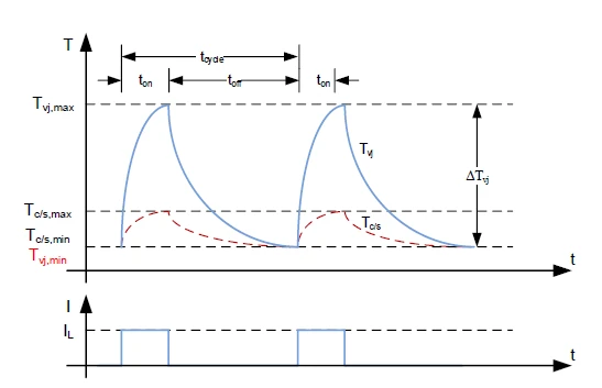
Repeated junction-temperature swing
Verification data
Power cycling verified at ΔTj 100 K
Model conversion to the typical ESS condition of ΔTj 60 K
Model estimate at 100 cycles per day
MODEL-BASED ESTIMATE
Expected lifetime is a model extrapolation based on results from a single test lot and does not represent a guaranteed product lifetime.
QUALITY ASSURANCE
Quality that reaches the customer — certification, documentation, change management
Certification
ISO 9001:2015Quality Management SystemQMS/15/R82/36152025.02 – 2028.02
ISO 14001:2015Environmental Management SystemEMS/2/R82/36152025.02 – 2028.02
Quality documentation supplied with the product
Datasheet & Simulation Model
- Guaranteed characteristics
- PLECS Model
- Thermal Model
Reliability Report & Certificate
- Qualification Report
- Failure Analysis Report
- Certificate Original
- Provided on request
PCN / PDN
- Product Change Notification
- Product Discontinuation Notification
- Long-term supply management
CLOSED-LOOP QUALITY
Quality does not end at delivery
Intake
We receive customer inquiries and field data.
- First response within 2 business days
Analysis · FA
- Electrical Analysis
- Thermal Analysis
- Structural Analysis
- Failure Mechanism Identification
- FA Report
Root cause · improvement
We identify the cause in design, process or assembly, then carry out corrective action and verification.
Recurrence prevention
Improvements are reflected in the following and managed with an 8D Report.
- Design Rule
- Process Condition
- Screening Criteria
Customer feedback
Results are confirmed with the customer and fed back into the next product development and the quality system.
Back into design and process
Built for Performance. Engineered for Reliability.
We develop power semiconductors that not only deliver high performance but sustain that performance over years of real-world operation.